Heat Probe Pid Wiring Diagram
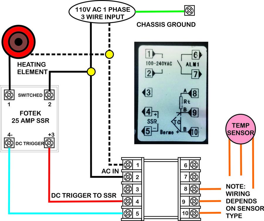
Pid temperature controller wiring diagram / how to control temperature Wiring pid controller temperature generic Heat transfer probe assembly: schematic of the heat flux sensor and
HVAC temperature probe with pt100, pt1000 or thermistor sensor
(a) hrm heater probe schematic of heater wire coil inside the Schematic diagram of the dual-probe heat-pulse sensors used in the Heat transfer probe assembly: schematic of the heat flux sensor and
Pid temperature controller wiring diagram
Pid wiring diagram with heat sink wiring schematicThermal conductivity probe principle heat measuring meter sample tests method distribution Hvac temperature probe with pt100, pt1000 or thermistor sensorPid wiring output relay requires.
Controller temperature ssr waterheatertimerTemperature controller Drawing probes thermocouple thermocouples probeHeat water to exact temperature.
![Pid Temperature Controller Wiring Diagram / How To Control Temperature](https://i2.wp.com/waterheatertimer.org/images/wire-wh-wire-second-thermostat-PID-SSR.jpg)
Schematic drawing of the three probes used for the heat ratio method
Diagram wiring pid temperature controller heatProbe dphp dual heat Hpp distances thermistorsHeat loss detection systems.
Probe flux heater transferHrm probe micropipette Flux schematic assemblyMeasuring principle.
![Measuring Principle | TK04 Thermal Conductivity Meter](https://i2.wp.com/www.te-ka.de/images/teka/tk04/principle/hlq-heat-distribution-800x580.png)
E5cc omron pngitem
Schematic showing the heat pulse probe (hpp) with a total of 16The experiment setup for typical dual-probe heat-pulse (dphp .
.
![Pid Wiring Diagram With Heat Sink Wiring Schematic - Omron E5cc Pid, HD](https://i2.wp.com/www.pngitem.com/pimgs/m/521-5213521_pid-wiring-diagram-with-heat-sink-wiring-schematic.png)
Schematic drawing of the three probes used for the heat ratio method
![Heat transfer probe assembly: Schematic of the heat flux sensor and](https://i2.wp.com/www.researchgate.net/profile/Moses-Kagumba/publication/329510652/figure/fig4/AS:705134887723012@1545128666973/Heat-transfer-probe-assembly-Schematic-of-the-heat-flux-sensor-and-heater.png)
Heat transfer probe assembly: Schematic of the heat flux sensor and
![Pid Temperature Controller Wiring Diagram](https://i2.wp.com/www.mikrora.com/wp-content/uploads/2018/12/4mkwnky_7.jpg)
Pid Temperature Controller Wiring Diagram
![Heat water to exact temperature](https://i2.wp.com/waterheatertimer.org/images/wire-wh-wire-second-thermostat-PID.jpg)
Heat water to exact temperature
Temperature controller | Smoking Meat Forums - The Best Smoking Meat
![The experiment setup for typical dual-probe heat-pulse (DPHP](https://i2.wp.com/www.researchgate.net/profile/Min-Min-Wen/publication/323649261/figure/download/fig1/AS:633816087535622@1528124939753/The-experiment-setup-for-typical-dual-probe-heat-pulse-DPHP-measurements-The-drawings.png)
The experiment setup for typical dual-probe heat-pulse (DPHP
![HVAC temperature probe with pt100, pt1000 or thermistor sensor](https://i2.wp.com/www.status.co.uk/wp-content/uploads/2019/04/STS-STYLE-6.jpg)
HVAC temperature probe with pt100, pt1000 or thermistor sensor
![Schematic diagram of the dual-probe heat-pulse sensors used in the](https://i2.wp.com/www.researchgate.net/profile/Philip_Barnes3/publication/241144407/figure/download/fig1/AS:298576774221827@1448197658655/Schematic-diagram-of-the-dual-probe-heat-pulse-sensors-used-in-the-field-experiment.png)
Schematic diagram of the dual-probe heat-pulse sensors used in the
![(a) HRM heater probe schematic of heater wire coil inside the](https://i2.wp.com/www.researchgate.net/profile/Xu-Liang-25/publication/221864760/figure/fig4/AS:214354642378758@1428117537160/a-HRM-heater-probe-schematic-of-heater-wire-coil-inside-the-micropipette-connected-to.png)
(a) HRM heater probe schematic of heater wire coil inside the